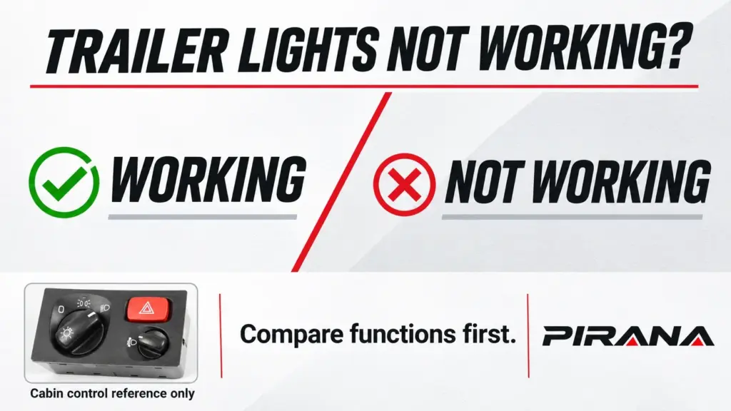
Brake lights work, but side markers are dead? That split points away from a complete loss of trailer lighting power. All trailer lights are dark? That points to a broader supply, connection or return-path investigation. Neither observation identifies a broken part. When trailer lights are not working, start with which functions fail and which still work, then follow the same failed function through the tractor, the pigtail and the trailer.
Distinguish brake lamps, turn signals, hazards, tail lamps, side markers and license plate lamps. A report that “the trailer has no lights” can hide a selective failure. Note whether the same group stays dead, flickers or changes after rain. These observations determine what needs comparison at each connection boundary.
A published example shows why that detail matters. In the TruckersReport thread “No trailer lights”, one driver reported dead side markers and license plate lights while tail lights, night lamps, hazards and brake lights still worked. Checking fuses and trying another pigtail did not resolve the complaint. The driver subsequently reported pins 2 and 6 as malfunctioning. This is one driver’s account, not a verified diagnosis or a pin map for another truck. Its useful lesson is the symptom split and the move toward checking individual circuits.
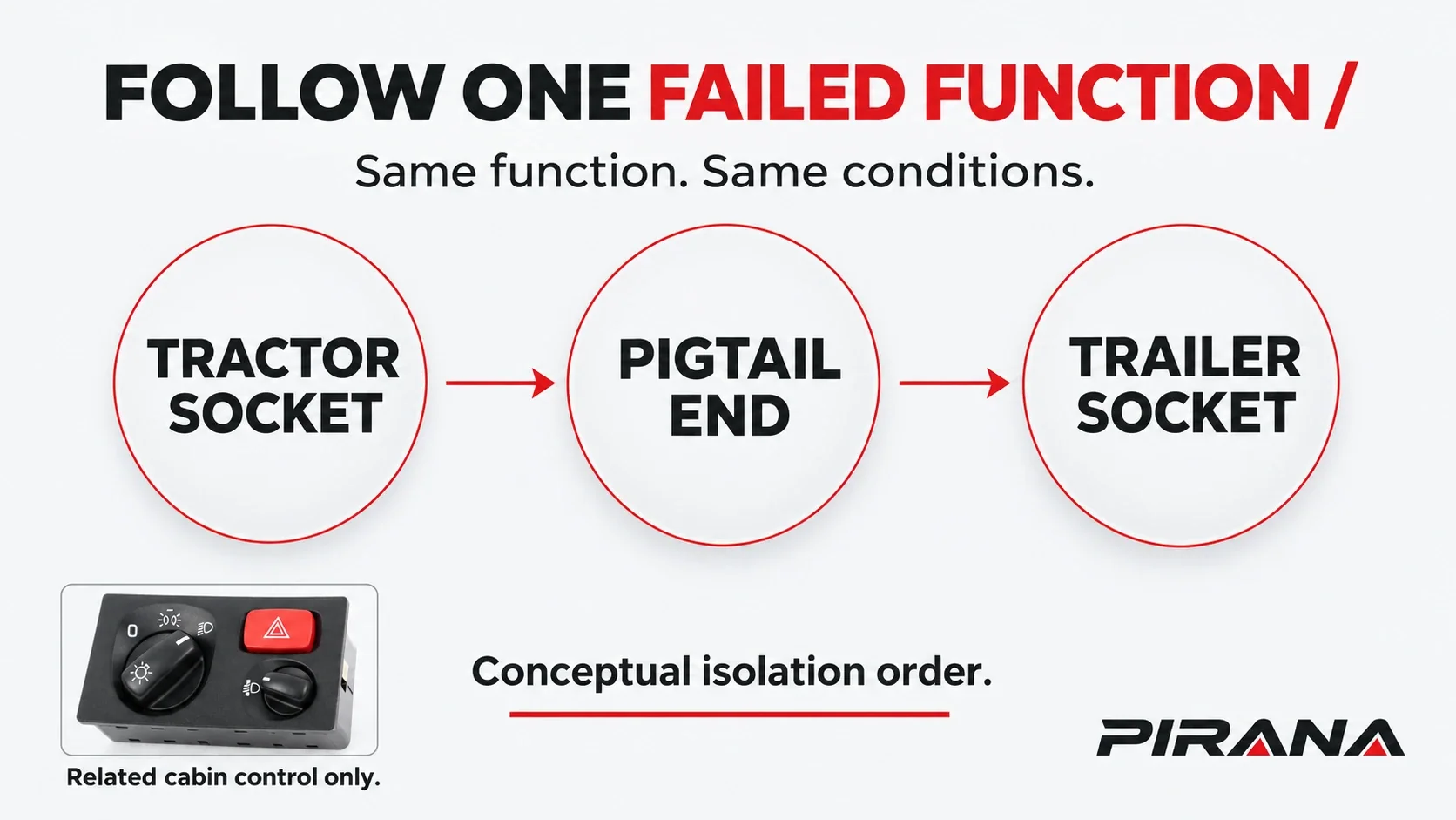
Isolate three segments, one function at a time
The tractor socket is the supply-side boundary. The pigtail is the coiled electrical connection cable between tractor and trailer. The trailer socket is the receiving boundary before the trailer-side distribution and lamps.
Keep the failed function and operating conditions consistent across the comparison. A brake-light result at one boundary cannot clear a marker-light complaint at another. Also, check the diagram or manual next to the trailer socket for the pin layout. If no applicable diagram is available, obtain the correct vehicle information. Layouts differ by brand and configuration; connector appearance alone is insufficient.
The sequence below describes what a vehicle-specific test result means, not how to probe a live connector. Have a qualified technician obtain electrical results using the applicable service information and suitable equipment. A driver can supply the observed lamp pattern without undertaking electrical testing. Do not manipulate connections while energized or try to recreate a fault while driving.
| Boundary checked in order | Result for the failed function | What it points to | Next decision |
|---|---|---|---|
| Tractor socket first | Expected output is missing under the documented conditions | Tractor-side output, socket or supply/control path; exact cause unconfirmed | Verify that boundary before blaming the cable or trailer |
| Pigtail output end, after tractor output is verified | The same function is missing at the cable output | Pigtail path or its tractor-side mating interface; exact component unconfirmed | Verify the cable and connection before proceeding downstream |
| Trailer socket/input, after cable output is verified | The function is lost across the trailer connection | Trailer input interface; further verification required | Distinguish socket/contact trouble from the connected trailer circuit |
| Trailer input, with the relevant supply and return verified | Input is available but the lamps remain out | Trailer-side distribution, return path or affected lamp branch | Continue with the trailer’s documented diagnostics |
First: establish the tractor socket result
If the expected function is missing at the tractor socket, that result points to the tractor-side boundary for investigation. It does not identify whether the socket, its connection, circuit protection or upstream control is responsible. There is not yet a verified output to follow through the pigtail.
If the expected function is present under the specified conditions, proceed to the cable output. Keep the result narrow: it covers the function and conditions checked. An intermittent complaint may not be present during a stationary check, and a result obtained without the connected trailer does not automatically settle behavior with it connected.
Grote’s technical handbook emphasizes checking the intervehicle power cable and establishing the integrity of power from the tractor before continuing with trailer diagnosis. The boundary order here applies that principle without reproducing a service procedure. Grote, troubleshooting trailer wiring harness systems, printed page 43.
Next: compare the pigtail output end
With tractor output verified, a missing corresponding function at the pigtail’s trailer-facing end points to the intervening cable path or tractor-side mating connection. It does not automatically condemn the coil. A contact interface can be involved even when the cable jacket looks sound.
If the corresponding function is available at the cable output under the documented conditions, proceed to the trailer socket. Avoid changing several items between comparisons. Replacing a fuse, changing the cable and disturbing both sockets together makes any improvement harder to attribute. One boundary result should determine the next investigation.
Then: assess the trailer socket and input
A verified cable-end result followed by a missing function across the trailer input connection points to that interface for further review. The trailer socket and its mating contact deserve attention, but the result still needs interpretation against the trailer’s circuit information.
If the relevant input and return path meet the documented requirements while the lamps remain out, the evidence points to the trailer-side circuit. That is a segment-level conclusion, not proof of failed lamps. The remaining investigation concerns how the affected function reaches the lights and returns through the specified ground path.
Tractor side: socket condition and circuit protection
Corrosion or damage visible at the tractor socket points to a connection area requiring verification. It does not show the electrical condition of every contact, and a clean-looking face does not establish the condition behind the receptacle. Record the location of visible deterioration rather than describing the entire socket as bad.
Tractor-side fuses and relays, where fitted, are other general investigation directions. Identify the protection and control arrangement from the actual tractor documentation. A missing output points to that circuit for review; it does not prove that a fuse or relay is the failed component. Equally, tractor lamps working normally does not establish that the separate trailer output is available. The Cascadia Driver’s Manual, Table 26.7 documents separate trailer-light fuses and relays on its covered configurations; it is an example, not a universal layout.
Keep dashboard controls out of the replacement decision until their role is established. A reported trailer-light failure does not establish that a headlight selector commands the affected trailer circuit on this configuration. The useful first finding remains the tractor socket result, not the name of the control the driver last touched.
Pigtail: oxidation, worn contacts and cable damage
Contact oxidation is a recognized trailer-lighting fault possibility. Grote’s handbook specifically discusses oxidation and corrosion at electrical connections. Visible deposits point to a contact condition needing investigation; they do not prove that deposits explain every failed lamp. Grote, printed page 43.
Worn contacts are another direction when connection quality is in question. A worn mating interface may affect one function while others remain available. That pattern points to a selective connection problem as a possibility, but cannot distinguish a cable terminal from the socket it meets. Both sides of the interface matter. Grote, “Vibration,” printed page 14 explains terminal wear and intermittent contact.
Visible cuts, abrasion, crushing or strain on the cable point to a location requiring qualified review. An undamaged outer jacket does not establish internal conductor condition. Conversely, visible jacket damage alone does not identify which lighting function has been interrupted. Relate the physical observation to the boundary results before choosing a repair. The Western Star 47X/49X maintenance manual, section 54-01 identifies cable damage and socket corrosion as inspection concerns for those vehicles.
Trailer side: socket, grounds and wiring
After the upstream function has been verified, trailer socket corrosion remains a possible entry-point problem. The receiving connection is distinct from the pigtail output, so a satisfactory cable-end result does not clear the interface when mated. A function lost there points to input-connection verification rather than immediate lamp replacement.
Ground problems belong in this segment review as well. In its own equipment troubleshooting chart, Midland lists damaged or disconnected ground cables, poor socket grounds and loose or corroded tractor-to-trailer ground connections among lighting-fault possibilities. Those entries support considering the return path; they are not a diagnosis of another trailer. Midland, Side Dump Trailer Operator’s Manual, printed page 81.
Trailer-side wiring can leave only a branch of lights affected. A repeatable group failure after the input is verified points to reviewing the relevant distribution and return paths. It does not prove that all lamps in that group failed together. The trailer’s documentation must establish which connections are actually shared.
Rain provides context, not a component verdict. Grote describes water entry through loose connections or damaged insulation and corrosion within wiring. Repeated wet-weather failures therefore point to moisture-exposed connections and wiring for investigation, potentially anywhere across the three segments. Dry-weather recovery does not identify which location needs repair. Grote, Major Causes of Lighting Failure, “Corrosion in the wiring”.
What working brake lights do not prove
Working brake lights do not prove that the trailer lighting circuit is fine. Different lighting circuits can fail independently. The TruckersReport case illustrates the reporting trap: several rear functions remained available while an extensive marker-light group was out. The working group could not clear the failed group.
Use that distinction throughout the isolation method. “Brake function available at the pigtail end” and “marker function unavailable at the tractor socket” describe different evidence. They should not be combined into “the cable is good” or “the trailer is bad.” Each finding points to a particular function and boundary requiring verification.
Nor does trying another part establish the fault location. If the symptom remains after a cable change, the unresolved complaint still needs boundary evidence. If it disappears after connections are disturbed, that points to connection-related investigation, not automatic proof that the removed cable was defective. Preserve the result and its conditions for the workshop.
For separate cabin-lighting questions, see Bad Headlight Switch Symptoms and Truck Headlight Switch Matching: Model & Connector. The Truck Cabin Switch Applications Guide maps cabin-control roles. PIRANA’s headlight switch category is related reading only. PIRANA does not supply trailer lights, and these links do not identify a fix for a trailer-light complaint.
FAQ
Why do my trailer lights not work but the brake lights do?
Different lighting circuits can fail independently. Working brake lights with dead markers or tail lamps points to a function-specific investigation rather than complete lighting power loss. It does not locate the failed part. Compare the affected function at the tractor socket, pigtail output and trailer input using the applicable service information.
How do I know if the problem is in the tractor or the trailer?
A missing expected tractor-socket output points to tractor-side investigation. Verified tractor output with the same function missing at the cable end points to the pigtail path or mating interface. Verified delivery through the trailer input with lamps still out points to the trailer-side circuit. Each result requires vehicle-specific verification before condemning a component.
Can a bad pigtail cause only some trailer lights to fail?
A problem affecting an individual contact or conductor can interrupt some functions while others remain available. Selective failure therefore points to the pigtail as one possibility, not the only one. Comparing the same function before and after the cable helps distinguish that possibility from tractor output or trailer-side trouble.
Why do trailer lights keep failing after rain?
The timing points to moisture entry, corrosion or an exposed connection or wiring problem requiring investigation. It does not isolate the pigtail: tractor and trailer sockets and trailer wiring also remain possible locations. Record which functions fail when wet and have the relevant boundary checked under documented conditions.
Will bad trailer lights fail a DOT inspection?
Trailer lights are a Department of Transportation (DOT) inspection item, and lighting defects can trigger an out-of-service order. Working brake lights do not clear other lighting defects. This is an inspection-risk statement, not a determination for a particular vehicle. CVSA, Operational Policy 14, lighting and unplugged power-cord sections.
References
- TruckersReport, No trailer lights, January 27, 2013. Driver-reported literature example, not confirmed repair evidence.
- Grote Industries, Know-How II: Vehicle Lighting – Installation and Troubleshooting, “Troubleshooting Trailer Wiring Harness Systems,” printed pages 14 and 43-46.
- Midland Manufacturing, Side Dump Trailer Operator’s Manual, electrical troubleshooting, printed page 81; equipment-specific examples only.
- Grote Industries, Major Causes of Lighting Failure, “Corrosion in the wiring.”
-
Commercial Vehicle Safety Alliance, Operational Policy 14, revised September 24, 2026, lighting and unplugged power-cord sections.
-
Daimler Truck North America, Cascadia Driver’s Manual, STI-478-6, February 3, 2022, Table 26.7; configuration-specific example.
- Daimler Truck North America, 47X and 49X Maintenance Manual, section 54-01, page 54/1, August 2020; inspection concerns only.