By James
An existing catalogue switch and a genuinely new design take different supply routes. If the selected model already exists, the work may concern branding, data and packaging through the private-label checklist. A model absent from the catalogue and requiring new tooling enters development instead.
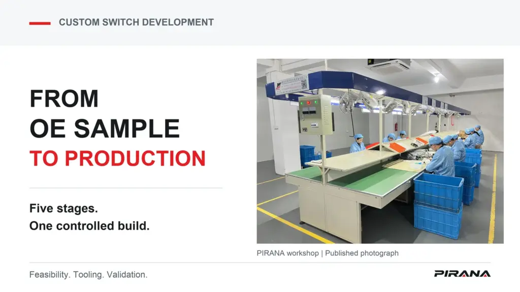
Custom truck switch development turns an OE sample into a specification that a factory can reproduce. This guide follows that route through sample review, tooling, trials, validation and production freeze. Cost and timing depend on four groups of decisions: geometry and tool architecture, material choices, validation scope, and expected volume. Those decisions need to be understood before requesting a project quotation.
PIRANA’s OEM/ODM routes and manufacturing overview provide the company context. The stages below describe a general switch-factory development model, not a PIRANA-specific price, schedule or disclosed internal process.
A public importer inquiry illustrates the questions behind that model. It explicitly asks about “Mould/Tooling Requirements”, “Certification Details” and “Sample Required”. The inquiry concerns modular electrical switches, not truck switches; it is evidence of buyer questions rather than proof of demand for a particular vehicle part. Public importer inquiry
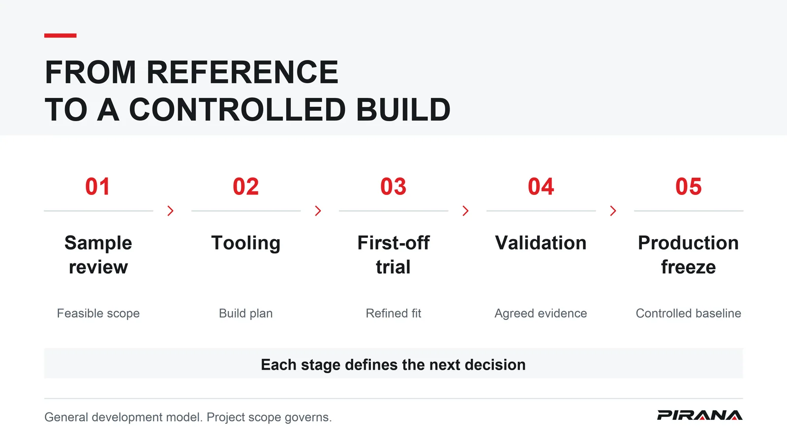
Stage 1: What the factory measures on your OE sample
Receiving a sample starts a feasibility decision. Its exterior provides a reference, but the factory needs a definition of how the complete switch must interface with the vehicle. The review groups that information into four areas.
Connector and terminal functions define the electrical interface. The required pin definitions must be established from the applicable information, rather than assigned from appearance. An external connector match alone cannot settle the switch’s functional role.
Mounting dimensions and clips define the mechanical interface. The factory needs to understand how the assembly locates, engages and remains retained in the intended mounting. A housing outline without the clip and mounting relationships leaves the tooling brief incomplete.
Function logic defines the required behavior. Where fitted, AUTO operation, indicators and interlocks belong in that definition. A control visible on the sample does not explain its full logic or prove that another configuration uses the same system.
Materials and the contact system define another part of the engineering requirement. These need a supported specification, not a guess from housing color or button feel. The relationship between these construction layers belongs in truck switch design: contacts, housings and connectors.
The factory’s output is a feasibility position: reproduce the agreed configuration, develop a modified configuration, or hold pending information. The drawing and functional brief must identify which path was chosen before tooling is committed.
For interchangeability, use the OE-identification guide. If reference review instead identifies an existing item in the Power Window Switch catalogue, confirm that route before funding a new tool.
Stage 2: The tooling decisions that set the price
Tooling translates the agreed part definition into a repeatable manufacturing approach. The factory needs to resolve the moulded parts, their geometry and the intended production demand together.
The number of housing pieces affects how many moulded components and tooling provisions are involved. Combining or separating pieces changes that task; an apparently simple exterior does not necessarily mean simple tooling.
Slides and inserts address features that cannot be formed and released through the simplest mould movement. Where needed, they introduce more tooling design, manufacture and adjustment. Part geometry therefore affects both the tool and the work needed to get usable parts from it. Injection-mould tooling cost drivers
Cavity count determines how many copies the tool forms in a moulding cycle. More cavities can improve piece economics when the demand and process justify them, but add investment and complexity. Increasing cavities is not automatically the most economical answer. The expected volume must support the tool concept. Multi-cavity tooling considerations
Tool steel selection also affects investment, machining work and service life. A more wear-resistant choice can suit a longer or more demanding production programme, while costing more to prepare. The choice must suit the part material and process; a grade name alone is not a mould-life guarantee.
Before paying tooling charges, put the following questions into the written project agreement:
- Ownership: Who owns the mould and associated tooling records?
- Exclusive use: Which designs, references or customers are covered by any agreed exclusivity?
- Maintenance and repair: Who is responsible for upkeep, repairs and the related decisions or charges?
- End of production: What happens to the tool when the programme ends or supply stops?
Payment alone should not be treated as an answer to those questions. The project needs an explicit agreement, without assuming an ownership or transfer rule.
What drives tooling cost and lead time
The factory’s quote follows the proposed build strategy. The table separates the main qualitative drivers; it is not a price list or a standard development calendar.
| Driver | What it affects | Direction to resolve before quotation |
|---|---|---|
| Part complexity | Tooling investment, development work and timing | More demanding geometry, components or tool movements can add design, machining and trial work. |
| Cavity count | Tool investment and piece cost | Additional cavities can improve output economics at suitable demand, with greater tooling commitment. |
| Steel selection | Tool preparation, cost and service life | Select suitable wear resistance and production durability for the resin, process and intended use. |
| Validation depth | Development effort and release timing | More requirements need more defined evaluation and evidence before production can be released. |
| Expected annual volume | Tool strategy and piece economics | The demand assumption changes which upfront investment can be justified over production. |
Tool-material choice is part of this production decision, not an isolated purchasing preference. Manufacturer guidance likewise treats tooling material as affecting cost, production suitability and how parts are developed. Tool-material considerations
A revised drawing, material requirement or annual-demand assumption can change the quotation basis. Keep that basis attached to the quote so a later comparison concerns the same development task.
Stage 3: First-off samples and why iteration is normal
The first tool trial, often called T1, shows what the proposed tooling produces. It is an engineering checkpoint before the production baseline is fixed.
The trial assembly needs to come together correctly. Clips must engage as intended, the operating feel needs to match the requirement, legends or printed markings need the right position, and terminals and connectors must mate as specified. These observations link the tool output to the original interface definition.
A sample can perform its basic function while still needing refinement in tolerance, clip engagement or feel. Conversely, acceptable appearance cannot clear an unresolved functional requirement. Plan for an iteration path rather than assuming the first moulded article is the final release sample. This does not imply a standard number of rounds for every switch.
The useful output is a recorded correction tied to the drawing, tool or assembly definition, followed by another check of the affected feature. Changing a sample without updating its definition would leave the next build uncertain.
Buyer sample approval remains a separate decision under the private-label checklist linked at the start. This stage explains why the factory may need another trial before it can present a stable version for that decision.
Stage 4: Validation before mass production
A switch that assembles and operates in a trial has cleared only part of the requirement. Validation asks whether the agreed configuration can meet its intended duty and environment.
Electrical load and endurance evaluation addresses the switching duty over repeated operation. The purpose is to reveal failures to make or break reliably as contacts and operating parts experience wear. The agreed electrical duty matters because an unloaded operating check cannot reproduce it. A successful demonstration at the desk cannot establish lifetime performance under the intended electrical conditions.
Environmental evaluation addresses the location in which the switch will work. Temperature changes can expose altered fit or operating feel; humidity can expose moisture-related instability; vibration can reveal weakened retention or intermittent interfaces. The project must define which conditions matter and what failure each evaluation is intended to detect. The names of these tests alone do not establish coverage or a passing result.
Material and flammability evaluation addresses the specified material properties and their relevance to the assembly. A material declaration and a finished-switch result answer different questions. UL’s plastics-testing guidance distinguishes burning behavior, ignition characteristics and property retention under exposure. The selected grade and relevant requirement must be identified before a statement about the product is made. Material-testing scope
These are validation purposes, not a universal switch test programme. Methods, conditions and acceptance requirements belong to the actual project. General automotive planning guidance also separates feasibility and development from product/process validation and production control. AIAG planning overview
Once evidence exists, its reading and applicability checks belong in how to read a power window switch test report. This development stage establishes why that evidence is needed.
Stage 5: Freeze, golden sample and change control
A production freeze establishes what the factory is expected to repeat. The golden sample is the physical reference for that agreed configuration, supported by its records. A sample on a shelf without a matching specification cannot control the next build.
Freeze the material grades, legend versions and packaging data alongside the product definition and golden sample. Production needs to know which material to use, which marking to apply and which data belongs to the released article. The physical sample and the written versions must describe the same build.
After freeze, a proposed material, legend or supplier change reopens the validation decision before release. Determine which requirements and evidence the change affects, complete the relevant verification, and update the controlled version. Treating every change as invisible would undermine the baseline; treating every change as technically identical would be equally unhelpful.
Material substitution is a clear example. A different source or formulation may affect performance and the evidence behind it. UL’s substitution guidance emphasizes assessment against defined material and performance boundaries. That supports controlled review, not automatic acceptance of an alternative. Material-change evaluation
The consequence reaches beyond the factory. Catalogue data must describe the released configuration, and a later return review needs to distinguish that version from an earlier build. Keep the production reference, material and marking versions, and the supplied data connected. Those records make a future change or complaint review about an identifiable article.
The IP line when developing from an OE sample
Developing a replacement that fits and provides the required functions is a different question from permission to reproduce a vehicle maker’s trademark, marked legends or protected structure. Possession of the sample does not resolve those permissions.
Raise any uncertain legend, marking or design feature before sampling. Technical feasibility does not settle its permitted use. This is a project boundary to resolve, not a claim of legal clearance or an infringement-avoidance service. WIPO overview of intellectual-property categories
FAQ
The switch I want is already in the factory’s catalogue – do I still need tooling?
An unchanged existing model generally follows the catalogue supply route. Branding, labels, data and packaging can be handled through the private-label checklist. A genuinely new model or a structural change can reopen tooling requirements. First confirm whether the existing reference matches the required configuration, then ask what the proposed customization changes.
Who owns the mould when I pay for tooling?
There is no project answer to assume from the payment alone. Agree in writing who owns the mould, the scope of any exclusive use, responsibility for maintenance and repairs, and what happens when production ends. Settle those questions before paying tooling charges. The commercial agreement must identify the arrangement; a development guide cannot determine ownership for the parties.
Why can’t the factory quote tooling from a photo?
A photo can support an initial discussion about the exterior. It does not define all the information needed for tooling. The factory needs the connector and terminal functions, mounting dimensions and clips, function logic, and material/contact requirements. Those define what must be developed and verified. A quote based on incomplete inputs remains dependent on resolving them.
How many sample rounds should I expect?
Plan for iteration, without assuming a fixed count or that the first-off sample is ready for production. Tolerance, clip engagement, operating feel and marking alignment may need refinement even when basic operation is present. Agree how trial observations become controlled corrections and how the affected features will be checked again. The required work determines the rounds.
What exactly gets frozen before mass production?
The golden sample, material grades, legend versions and packaging data form part of the released configuration with the product specification. Establish the change-control rule as well. A later material, marking or supplier change must reopen review and the affected validation before release, with the updated version linked to production. Freezing a sample alone leaves the rest of the build undefined.
Sources
The factory-side sequence is a general development model. These sources do not provide PIRANA prices, development periods or model-specific test results.
- PIRANA OEM/ODM, Manufacturing and Quality Control pages; the design and private-label guides. The permitted internal links appear at the relevant decisions above.
- go4WorldBusiness, public modular-switch importer inquiry – buyer-question context only.
- Protolabs, injection-mould cost drivers, multi-cavity considerations and tool-material considerations – qualitative relationships only.
- AIAG, planning-process overview
- UL Solutions, plastic-material testing and material-substitution evaluation
- WIPO, intellectual-property categories