By James
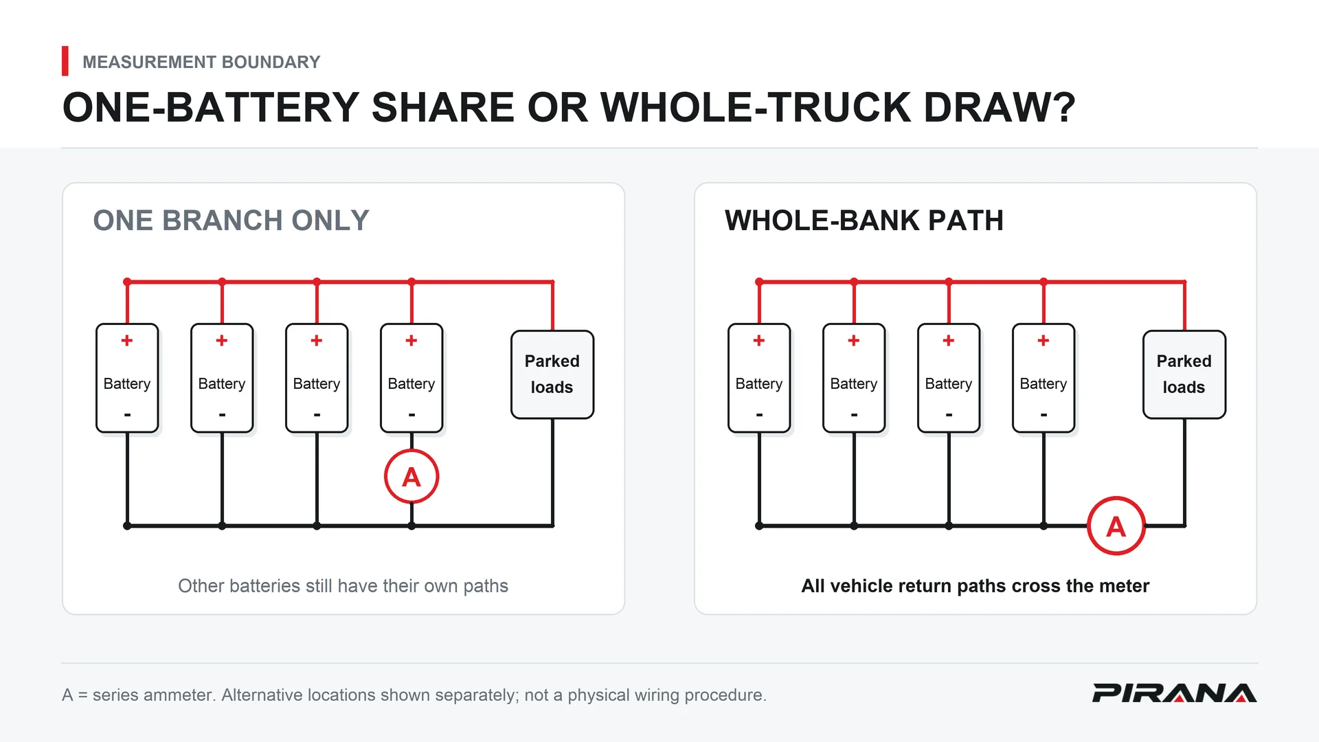
A four-battery truck changes a parasitic draw test in three important ways: check each battery before blaming an external load, measure where the complete bank’s vehicle current passes, and use the disconnect-switch result to separate downstream loads from bypass feeds or battery problems. Putting an ammeter into one battery branch can give a believable reading that is not the truck’s total draw.
The TruckersReport thread “Parasitic draw? Pete 589” captures the question: an owner reported replacement batteries, a new alternator and kill switches, yet a discharged bank after parking. Knowing the single-battery method had not resolved where to measure a four-battery truck.
This is a bank-testing and circuit-isolation framework. Use the truck’s service procedure for actual cable work. Battery-bank short-circuit current is extremely high: remove metal jewelry and protect tools against bridging terminals before work begins.
Why four batteries change the test
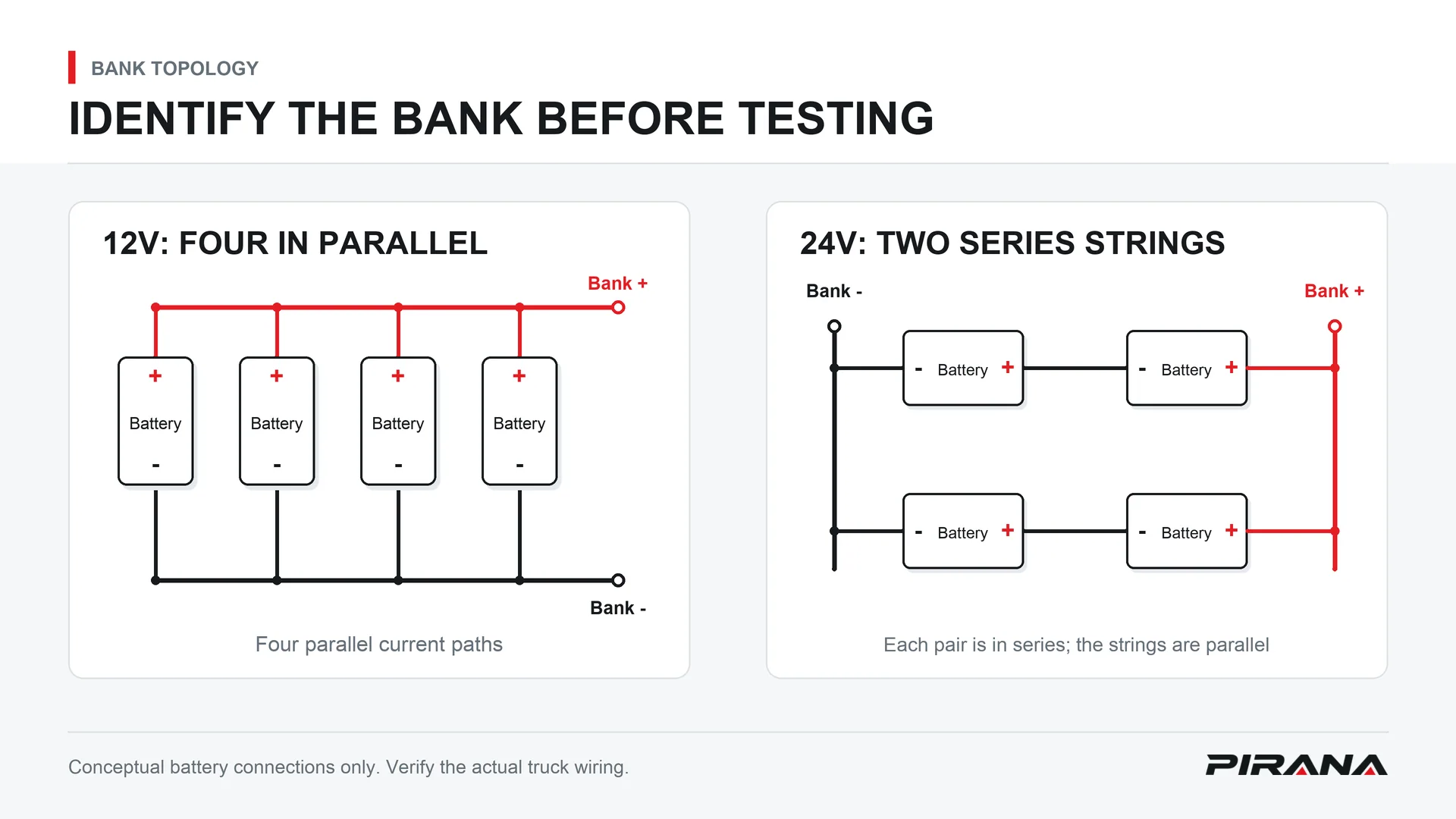
Identify the wiring before choosing a measuring point. Four batteries do not establish the bank voltage or the number of parallel current paths.
| Configuration to verify | How the bank is arranged | What a branch measurement misses |
|---|---|---|
| 12V four-parallel bank, a common US truck arrangement | All four batteries share the bank’s positive and negative connections | Current supplied through the other batteries’ branches |
| 24V series-parallel bank | Two batteries form each series string; the two strings are connected in parallel | Current through the other series string |
These are configuration examples, not instructions to reconnect an unfamiliar bank. Victron’s Wiring Unlimited, battery-bank wiring explains the series/parallel distinction. For the wider system-versus-component voltage boundary, see 12V vs 24V Truck Switches.
The measuring-point trap
If you interrupt only one battery’s connection while the other parallel paths remain available, the ammeter measures that branch’s contribution. It does not measure the complete vehicle load. Do not multiply that reading by four: the shares need not be equal.
The whole-bank test belongs at the verified common feed or common return boundary through which all vehicle current passes. With several ground cables, a convenient negative post is not automatically that boundary. Map the engine, frame and other vehicle ground paths before assuming the meter includes them all.
International’s IK0800025: Measuring Parasitic Battery Load, revision 15, provides a four-battery example with multiple ground paths brought into the measurement. Its principle is complete vehicle-current coverage; its exact cable arrangement must not be copied onto a different truck.
An individually isolated battery test answers a different question: whether that battery retains charge and meets its specified test requirements. It is not a substitute name for measuring parked-truck draw.
Step 0 – rule out the bank itself
A faulty battery can pull down otherwise serviceable batteries connected with it. New batteries are not exempt: a defective cell or an individual battery that cannot retain charge can still make the group look like it has an external drain.
Follow the truck and battery manufacturer’s isolation procedure, identify each physical battery, and separate the inter-battery connections so the units can be assessed individually. Charge and test them as specified, then compare their voltage and condition after the prescribed isolated rest period. Include the appropriate individual load test. Do not invent a rest duration or acceptance voltage from another battery type.
Record each battery’s identity, initial condition after charging, rest interval, resting voltage and load-test result. Keep the units separated for the retention comparison: leaving them connected allows one battery to influence the others and defeats that part of the investigation.
A respondent in the same TruckersReport discussion described a K100 that operated during the week but failed after time parked. Earlier battery tests had passed; after the batteries were disconnected from each other, one was dead on the third day. Replacing it reportedly resolved the complaint. That is an owner’s experience, not a universal three-day test specification.
Resolve an individual battery failure before interpreting vehicle draw. Current circulating within the bank is a different problem from current leaving the bank to power the truck. A whole-vehicle ammeter reading alone cannot clear every battery inside the group.
Set up and let the truck sleep
With battery health established, restore the documented bank configuration and identify the complete vehicle-current path. Switch off the ignition and intended loads. Prepare access under the service procedure so later activity does not repeatedly wake the truck.
For a series-ammeter method, select the meter’s highest suitable DC-current range and confirm the leads are in its documented current and common sockets. Observe the meter’s current limit; an unexpectedly high load is a reason to stop, not to force the test through the instrument.
At a verified common negative test boundary, the meter bridges the interrupted connection between the bank negative and the complete vehicle-side return. Every relevant ground path must be included under the applicable service method. Never connect an ammeter directly across battery positive and negative.
Do not crank the engine or switch on large loads with the ammeter in series. This can damage the meter or its fuse. Fluke’s parasitic-drain multimeter guidance supports the current-range, socket and high-load precautions. Its generic current figures are not truck acceptance limits.
Key off does not mean asleep
Modules can remain awake after the key is removed. A reading taken during shutdown can therefore misrepresent the parked condition you are trying to assess. Note the elapsed time and use the truck manufacturer’s sleep-state requirements before judging the current.
The 1A Auto demonstration describes about 10 minutes for older vehicles and up to 1 hour for newer vehicles. Those are passenger-car demonstration figures, not a heavy-truck waiting rule. Use the actual truck’s service information for both sleep time and allowed draw.
There is no universal normal-current number for this article’s four-battery trucks. Current above the applicable manufacturer-specified allowance, measured in the required state, is abnormal. Adding batteries does not turn a branch reading into a valid whole-truck acceptance test.
Isolate the circuit
Once an excessive whole-bank draw is established after sleep, locate the path responsible. Keep the original setup and conditions recorded so a later change can be compared with the baseline.
| Method | Can it disturb sleep? | Useful role and limitation |
|---|---|---|
| Monitor total current while removing fuses individually | Removing or reinserting a fuse can change module state | A repeatable drop points to the circuit affected by that fuse; wait for sleep again before confirming the interpretation |
| Measure voltage drop across an installed fuse | Avoids the disturbance caused by pulling that fuse, provided other test activity does not wake the truck | Identifies current through a fuse under the applicable service method; interpretation depends on the actual fuse and documentation |
For the first method, record the suspect fuse and the current change. A falling reading identifies a circuit to investigate, not a component to replace. A circuit may serve several devices, and a module-state change can affect the result. Subaru’s 07-236-25 bulletin specifically warns that reinserting fuses can wake modules and require another sleep period; its vehicle-specific limits are not used here.
The installed-fuse method uses voltage measurement, rather than putting a current-mode meter across a fuse. GM’s TechLink explanation of parasitic-draw testing describes that alternative. This article provides no fuse-size-to-voltage-drop conversion table: use applicable manufacturer information, not a generic chart transferred from another fuse design.
After identifying the suspect circuit, verify its connected loads and the cause of the unwanted draw. Then repeat the whole-bank test under the same documented sleep conditions after repair.
The alternator branch
A failed alternator diode can allow battery discharge with the key off. Midtronics explains that reverse-current mechanism in its alternator-diode guidance. A new alternator does not justify skipping the branch when the evidence points there.
The diagnostic comparison is total key-off draw before and after the alternator’s B+ output connection is safely isolated under the truck’s service procedure. If the abnormal draw disappears, that points to the alternator branch, including its diode circuit, for confirmation. It does not by itself prove which internal diode failed.
B+ cable handling requires the prescribed battery isolation and protection against shorting. It is not a live-cable disconnection test, and the engine must remain off. This comparison identifies a diagnostic direction; it supplies no alternator repair instructions.
What the disconnect-switch result tells you
First establish that the disconnect actually opens the intended main circuit. A handle at OFF is not proof that every vehicle load has been isolated. Interpret the following results only after the switch’s operation and wiring scope are verified.
| Verified result | What it points to |
|---|---|
| Abnormal draw stops with the main circuit open and returns when closed, after the required sleep period | A load downstream of that isolation boundary; continue circuit isolation |
| Batteries still lose charge while the intended main circuit is genuinely isolated | A load hardwired directly to the batteries around the switch, or a battery-retention/internal bank problem |
The TruckersReport discussion raises both direct-connected equipment and battery faults. That distinction prevents the wrong conclusion that another or larger kill switch must solve the problem. Revisit Step 0 for battery retention, and identify any feed that bypasses the isolation boundary.
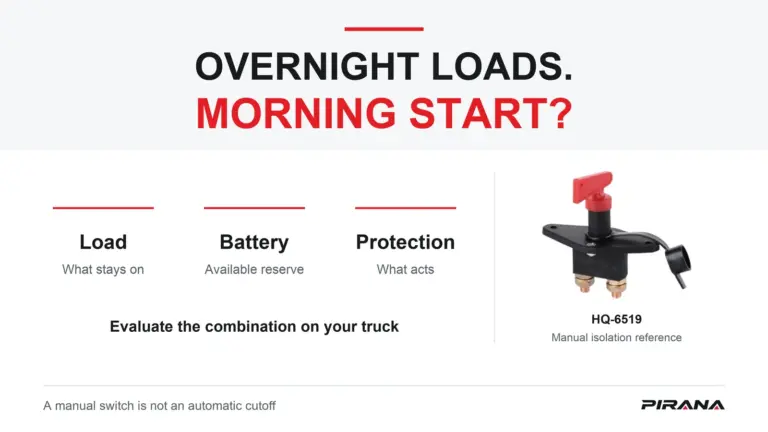
After the drain is found and repaired, manual isolation can have a role during long parking periods, together with battery-manufacturer-prescribed maintenance charging. It does not locate or repair the unwanted load. A bypass-fed accessory remains outside the switch’s protection scope.
PIRANA’s Battery Switch category is relevant to that isolation role. The following are current catalogue references, not a buying shortlist or a recommendation for the truck under test:
| PIRANA model | OE reference | Application stated on the product page |
|---|---|---|
| HQ-6502 | WG9100760100 | Steyr |
| HQ-6519 | 81.25506.6033 | F3000 |
| HQ-6520 | DZ95189763010 | M3000 |
These records do not establish suitability for an unspecified four-battery bank. Selection questions belong in Commercial Truck Battery Disconnect Switch Selection. Diagnosis still has to find and correct the faulty circuit; manual switching is not automatic drain detection or a cure.
Usual suspects on a parked truck
Treat these as investigation directions, not a probability ranking. Verify each against the actual wiring and the circuit-isolation methods above:
- Under-hood light: inspect for an unintended glow and confirm its circuit against the whole-bank baseline; a respondent in the forum reported finding this overlooked load.
- Sleeper lights and refrigerator: identify their actual parked supply and confirm the effect of isolating the relevant circuit after sleep.
- Inverter: verify its supply path and compare draw with that branch safely isolated; an unused appliance does not establish that the inverter feed is disconnected.
- GPS or telematics terminal: identify direct battery feeds as well as switched circuits, then confirm whether the suspect path accounts for the excessive draw.
- Dash camera or monitoring device: a dark display is not evidence of electrical isolation; use the documented supply circuit and a repeatable current comparison.
Record what changed, allow the truck to sleep again when necessary, and confirm the final whole-bank result. The component name or an apparently off screen is not the measurement.
FAQ
Can I test at just one of the four batteries?
Not by interrupting only one parallel branch and treating its reading as the total. That measures the branch contribution while other paths remain. Measure the verified whole-bank feed or return boundary. Separately isolating and testing each battery assesses its own condition; label those results accordingly.
What parasitic draw is normal for a semi truck?
There is no universal number for every semi truck or four-battery bank. Use the exact truck manufacturer’s allowed current and required sleep conditions. Passenger-car demonstration values must not be transferred to a heavy truck, and the reading must include the complete vehicle load.
The batteries and alternator are new – can it still not be a draw?
Yes. An individual battery fault can pull down the connected group, so replacement history does not eliminate Step 0. Isolate and assess each battery’s charge retention and specified load-test condition before concluding that an excessive external parked load exists.
Will a battery disconnect switch fix a parasitic draw?
No. Manual isolation can interrupt the circuits within its verified scope during parking, but it neither finds nor repairs the drain. A direct battery feed may bypass it. Find the unwanted load, repair its cause and verify the whole-bank result rather than using the switch as a substitute for diagnosis.
How do I tell if it is the alternator draining it?
Under the truck’s service procedure, compare total key-off draw before and after safe isolation of the alternator B+ output. Disappearance of the abnormal draw points to that branch, including possible diode leakage. Confirm the cause through the applicable diagnostics; do not disconnect a live B+ cable or run the engine during the series-meter test.
Sources
- TruckersReport, Parasitic draw? Pete 589, April 2020, original complaint and respondent experiences; not numerical specifications.
- Victron Energy, Wiring Unlimited: Battery bank wiring, series/parallel principles.
- International/Navistar, IK0800025: Measuring Parasitic Battery Load, revision 15, February 2, 2018, four-battery ground-path example.
- Fluke, How to Find Parasitic Battery Drain with a Multimeter, current-mode setup and safety only.
- 1A Auto, Battery Always Dead: How to Perform a Car / Truck Parasitic Draw Test, April 6, 2020; passenger-car demonstration context, not heavy-truck acceptance limits.
- Subaru, 07-236-25, October 23, 2025, fuse-reinsertion wake-up caution only.
- General Motors, TechLink: New Circuit/System Testing for Parasitic Draws, Mid-December 2020, installed-fuse method only.
- Midtronics, What Are Diodes and What Are They Used For?, alternator reverse-discharge mechanism.
- PIRANA, Battery Switch category and HQ-6502 / WG9100760100 / Steyr, HQ-6519 / 81.25506.6033 / F3000, and HQ-6520 / DZ95189763010 / M3000 product records, checked November 10, 2026; links are in the disconnect-switch section.