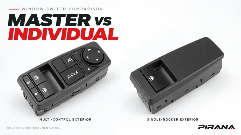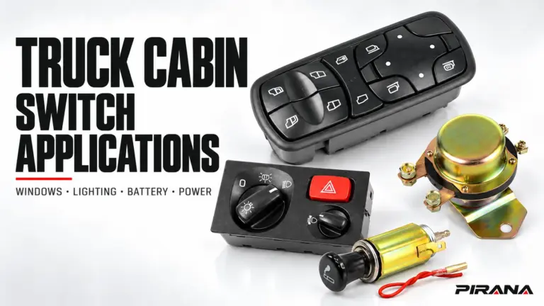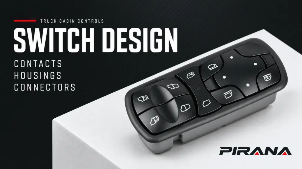
Truck switch design brings three requirements together: contacts suited to the electrical duty, a housing and operating mechanism that preserve the intended movement, and a connector that maintains the vehicle-side interface. A material name, positive button click or matching plug outline cannot establish that the complete assembly meets its application.
Keep two meanings of “contact” separate. Internal switch contacts make, break or encode a command inside a design that uses them. Connector terminal contact is the mating interface between the switch and the vehicle harness. A fault at either location can interrupt operation, but the evidence needed to identify the cause is different.
For distributors and technical buyers, the useful question is how these layers work together—and which exact drawing, specification or validation record supports a construction claim. This is a general engineering explanation, not a cutaway of a PIRANA product or a vehicle repair procedure.
Electrical duty comes before contact material
First establish what the control actually does in the vehicle circuit. A direct-load switch, an input to a relay/control unit and an electronic command assembly have different duties. The same visible rocker does not identify which architecture is present.
As a truck-specific example, Scania’s 24 October 2019 GB Electrical Interfaces guide, p. 7, describes its Bodywork Communication Interface (BCI), including configurable inputs, logic and communication with vehicle control units. It shows why a driver’s control can participate in an electronic command path. It does not establish the architecture of a PIRANA window switch or every Scania cab control. See the Scania BCI description.
This distinction changes the meaning of a contact rating. OMRON’s basic-switch technical cautions, under Contact Load, Load Types and Selecting Correct Switch, explain that load and inrush conditions affect contacts, and that a large-current switch is not automatically suitable for microcurrent service. These are component engineering principles, not a specification for a truck or PIRANA part.
The practical implication is to resolve the circuit duty before interpreting “heavy-duty contacts.” A high maximum-current figure alone does not answer a low-level signal requirement. Likewise, a voltage label does not define the load, switching conditions or control interface. The 12V vs 24V truck switch guide addresses that wider rating-verification task.
Contact behavior depends on the surface and the duty
Electrical conduction occurs at the working interface, so the bulk metal name is only part of the explanation. Surface condition, contact geometry and the applicable electrical conditions matter together.
OMRON’s basic-switch technical guide, in its microload selection and contact-failure discussion, identifies contamination and insulating surface films as possible causes of unreliable conduction. At low signal levels, a contact can therefore be unsuitable even when its maximum current capacity appears ample. The guide does not support a universal ranking in which one contact metal is best for every duty.
For an exact part, “silver contacts,” “copper conductors” or “gold finish” needs context: which element carries that material, which grade or finish is specified, and under which electrical conditions was the assembly evaluated? A finish on a connector terminal is not automatically the material of the internal switching contact.
No exterior photograph resolves those questions. Material and finish records describe construction; a relevant functional or durability record evaluates the specified assembly under its stated conditions. Neither should be replaced with an unsupported “OEM quality” label.
The housing is part of the operating geometry
The housing and actuator structure do more than determine how a switch looks in the trim panel. In a contact-operated design, they help maintain the relationship between the user’s movement and the intended switching action. Mounting and retention also keep the assembly in its specified position relative to the panel and harness.
Assess the relevant design functions separately:
- Actuation: the intended travel, return and relationship between the rocker or button and its switching/command mechanism.
- Support and alignment: the locations and tolerances that position the operating parts and electrical interface.
- Vehicle installation: locating features, clips and mounting surfaces that retain the approved assembly.
- Insulation and environmental requirements: the specified material grade and assembly design for the actual location and conditions.
These are questions for the controlled design record, not claims about hidden features in a photographed product. A black moulded housing does not identify its resin formulation, reinforcement, thermal performance or sealing. A named resin or a material test also does not establish the performance of the complete fitted switch.
Tactile consistency is useful evidence about operation under the conditions observed. It does not measure contact resistance, prove command recognition or establish long-term electrical performance. Conversely, a part can have the expected electrical function during a check while its mounting or actuator behavior remains unacceptable against the agreed specification.
Connector fit and terminal engagement are different questions
The external connector housing establishes a mating arrangement, including the relevant shape, orientation and keying. The terminals must also be the correct type, occupy their intended positions and maintain the required engagement. Where separate housing latches, terminal locks or seals are specified, their functions should not be collapsed into “the plug fits.”
A bounded automotive example makes the distinction concrete. In its August 2018 TechTIPS, p. 1, Subaru described a 2014 Forester window complaint caused by a partly displaced connector locking arrangement. Terminals could back away from the master-switch pins, and restoring the locking arrangement restored operation. This was a diagnosed case in that vehicle, not a truck-wide repair instruction. See Subaru’s terminal-retention case.
The case illustrates a causal boundary: an apparent switch symptom can originate at the harness interface without establishing an internal switch-contact defect. It does not mean every connector uses the same lock or permits the same remedy.
For replacement matching, connector shape and pin count remain preliminary observations. Terminal functions, electrical architecture, version and vehicle application still need their own evidence. Use the OE-number and connector identification guide for that separate matching task.
Local heating links electrical and mechanical conditions
For a current-carrying interface, resistive dissipation follows P = I²R, where P is power, I is current and R is resistance. At the same current, an increase in interface resistance increases local resistive dissipation. Actual temperature rise also depends on heat dissipation, surrounding conditions and the loading arrangement.
TE’s AMP Metrimate catalogue, revised June 2008, pp. 3–5, explains this thermal relationship for its connector context. The principle helps explain why current capacity cannot be assessed independently of the interface and thermal conditions. Its product ratings and numerical limits are not truck-switch or PIRANA specifications. See TE’s connector temperature discussion.
This is a mechanism, not a diagnosis. A discoloured connector or melted housing is an observation requiring investigation; it does not by itself identify excessive contact resistance as the cause. A circuit fault, unsuitable duty or other damage may require different evidence. Nor does the formula supply a universal safe resistance, test current or allowable temperature.
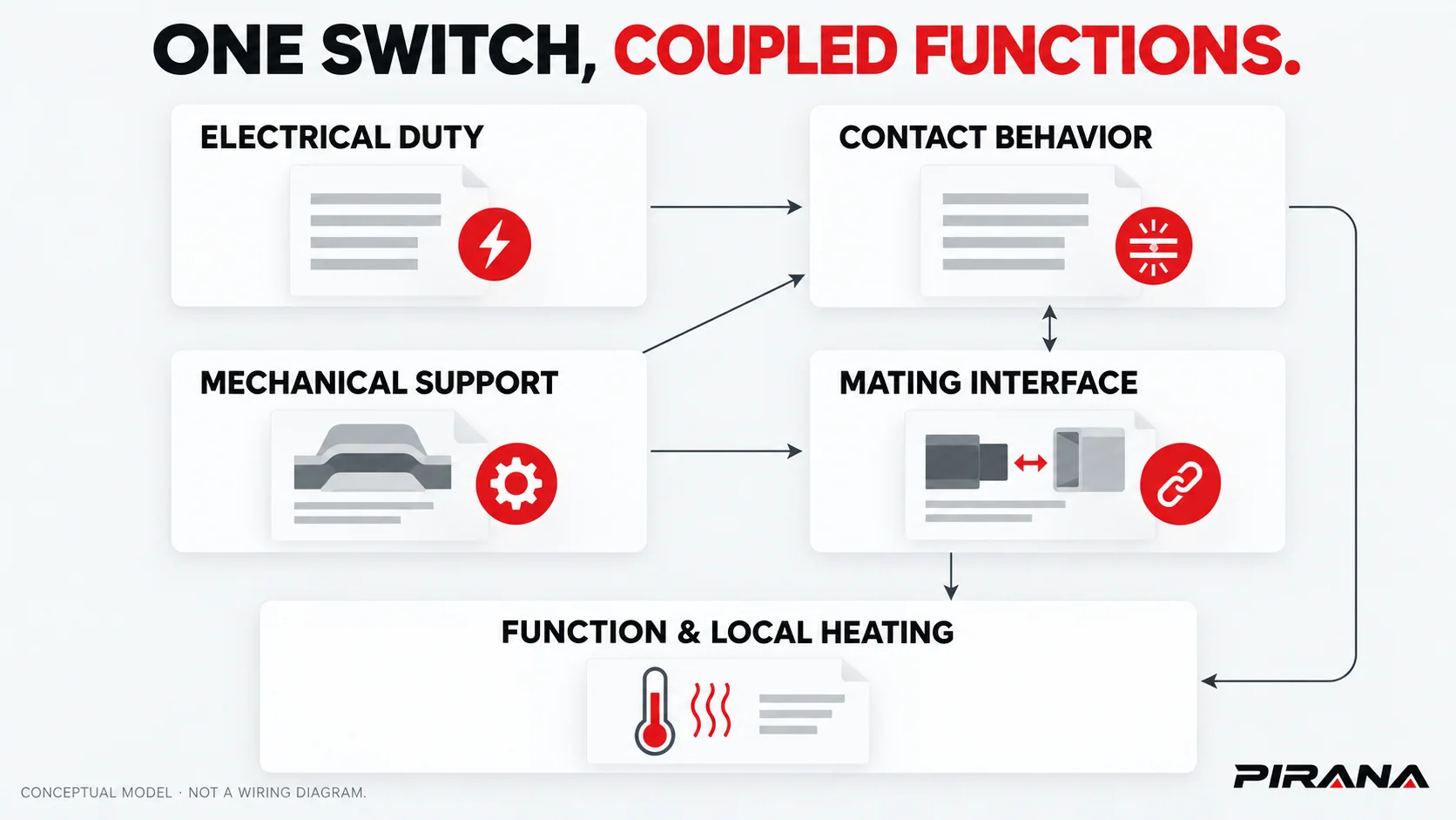
The coupled-design lesson is that electrical and mechanical observations must be interpreted together. An engagement problem can affect the electrical interface; electrical heating can accompany visible material damage. The observed damage alone does not establish where the sequence started. Use the applicable vehicle diagnostic method for a fault, rather than probing, bending, lubricating or bypassing an unknown interface from a general design article.
Turn construction claims into specific evidence questions
The table below is a reading aid for drawings and product records. It separates what a construction claim addresses from what remains unproved; it is not an incoming-inspection test plan.
| Claim or observation | Design question it raises | Evidence that resolves the question | What it cannot establish alone |
|---|---|---|---|
| “High-current contacts” | What load, switching conditions and circuit role were specified? | Exact-version rating/specification and relevant validation conditions | Reliable microload operation or vehicle compatibility |
| Named contact metal or finish | Which internal or connector element uses it, and why is it appropriate? | Material/finish record linked to the drawing and actual duty | Complete assembly life or a universal quality ranking |
| Firm rocker action and consistent return | Does travel and actuation meet the design requirement? | Operating-mechanism requirements and the relevant assessment record | Electrical continuity, command recognition or endurance |
| Matching connector outline | Do keying, terminal type, retention and assigned functions match? | Interface drawing plus vehicle and part-version records | Correct operation from appearance or pin count |
| Named housing resin or a sealing claim | What assembly, location and conditions does the statement cover? | Specified grade/design and applicable assembly validation | Performance of every variant or an ingress rating from appearance |
| Heat damage or intermittent operation | Where is the fault, and which mechanism is established? | Vehicle-specific diagnosis with relevant part/interface evidence | Proof that the switch’s internal contacts are the cause |
Consider an illustrative enquiry: a sample clicks consistently, its plug outline matches the original and the supplier describes a contact material. Those three observations address different questions. They still leave the circuit role, exact terminal functions, relevant material location and duty-specific performance unresolved. The next step is to request those records, not combine the observations into a compatibility claim.
PIRANA’s HQ-6901 catalogue example shows an exterior control layout; that view does not expose its internal contact system or prove a rating. Use the power window switch catalogue to identify the reference, then request the relevant exact-version information through the downloads/document request page. For executing an agreed sample check, continue to the separate truck switch quality inspection checklist.
References
- Scania GB — Bodybuilder Quick Reference Guide: Electrical Interfaces, 24 October 2019, p. 7.
- OMRON — Basic Switches: Safety Precautions, Contact Load, Load Types and Selecting Correct Switch; Basic Switches: Further Information, microload selection and contact-failure discussion.
- Subaru of America — August 2018 TechTIPS, p. 1, diagnosed 2014 Forester connector-retention case.
- TE Connectivity / Tyco Electronics — AMP Metrimate Pin and Socket Connectors, Catalog 82045, revised June 2008, pp. 3–5.
REFERENCED IN THIS GUIDE
Products mentioned in this article
These published catalogue references are included because they are discussed in this guide. A reference is a starting point for identification; confirm the exact OE number, connector and vehicle configuration before ordering.
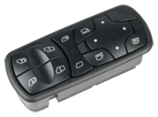
Power Window Switches
Power Window Switch — OE A9438200097
PIRANA Part No. HQ-6901 · OE: A9438200097
View product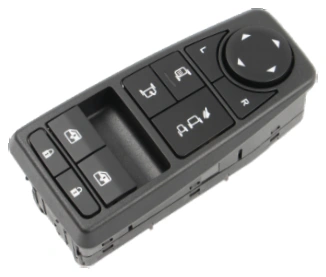
Power Window Switches
Power Window Switch — OE 81258067107 / 81258067092
PIRANA Part No. HQ-6918 · OE: 81258067107 81258067092
View product